F.2.1.2
The Backwater Analysis Method is used to analyze the capacity of both new and existing pipe systems to convey the required design flow. For both new and existing systems, structures shall be demonstrated to contain the headwater surface (hydraulic grade line) for the specified peak flow rate.
This method incorporates a re-arranged form of Manning's equation expressed in terms of friction slope (i.e., the slope of the energy grade line, in units of ft/ft). The friction slope is used to determine the head loss in each pipe segment due to barrel friction, which can then be combined with other head losses to obtain water surface elevations at all structures along the pipe system.
The backwater analysis begins at the downstream end of the pipe system and is computed back through each pipe segment and structure upstream. The friction, entrance, and exit head losses computed for each pipe segment are added to that segment's tailwater elevation (the water surface elevation at the pipe's outlet) to obtain its outlet control headwater elevation. This elevation is then compared with the inlet control headwater elevation, computed assuming the pipe's inlet alone is controlling capacity using the methods for inlet control presented in F.2.2 Culverts. The condition that creates the highest headwater elevation determines the pipe's capacity. The approach velocity head is then subtracted from the controlling headwater elevation, and the junction and bend head losses are added to compute the total headwater elevation, which is then used as the tailwater elevation for the upstream pipe segment.
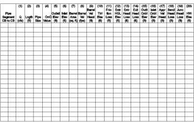
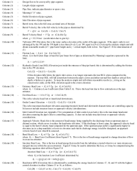
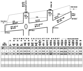
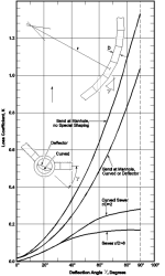
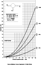
The Backwater Calculation Sheet in Figure F.4 may be used to compile the head losses and headwater elevations for each pipe segment. The numbered columns on this sheet are described in Figure F.5. An example calculation is performed in Figure F.6. Refer to Figure F.7 and Figure F.8 regarding bend head losses and junction head losses, respectively.
This method should not be used to compute stage/discharge curves for level pool routing purposes. Instead, a more sophisticated backwater analysis using a computer software program is recommended for that purpose.
Figure F.4. Backwater Calculation Sheet.
Figure F.5. Backwater Calculation Sheet Notes.
Figure F.6. Backwater Pipe Calculation Example.
Figure F.7. Bend Head Losses in Structure.
Figure F.8. Junction Head Loss in Structure.
Computer Applications
There are a number of commercial software programs for use on personal computers that use variations of the Standard Step backwater method for determining water surface profiles. The most common and widely accepted programs include HEC‑RAS, published and supported by the United States (US) Army Corps of Engineers Hydraulic Engineering Center, and Stormwater Management Model (SWMM), originally published by US Environmental Protection Agency.
