F.2.3.2
The Direct Step backwater method may be used to compute backwater profiles on prismatic channel reaches (i.e., reaches having uniform cross‑section and slope) where a backwater condition or restriction to normal flow is known to exist. The method may be applied to a series of prismatic channel reaches in secession beginning at the downstream end of the channel and computing the profile upstream.
Calculating the coordinates of the water surface profile using this method is an iterative process achieved by choosing a range of flow depths, beginning at the downstream end, and proceeding incrementally up to the point of interest or to the point of normal flow depth. This is best accomplished by the use of a table (see Figure F.15 and the accompanying example in Figure F.16) or computer programs.
Figure F.15. Open Channel Flow Profile Computation.

Figure F.16. Open Channel Flow Profile Computation (Example).
")
To illustrate analysis of a single reach, consider the following diagram:
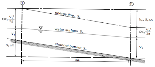
Use Equation F.9 to calculate the total head at cross‑sections 1 and 2.
Equation F.9. Total head for a single reach (Direct Step Analysis Method)
where:
 x = distance between cross‑sections (ft)
y1, y2 = depth of flow (ft) at cross‑sections 1 and 2
V1, V2 = velocity (fps) at cross‑sections 1 and 2
 ,
,  = energy coefficient at cross‑sections 1 and 2
So = bottom slope (ft/ft)
Sf = friction slope = (n2V2)/(2.21R1.33)
g = acceleration due to gravity, (32.2 ft/sec2)
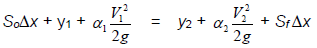
If the specific energy E at any one cross‑section is defined in Equation F.10.
Equation F.10. Specific energy for a single reach (Direct Step Analysis Method)
and assuming  = = where is the energy coefficient that corrects for the non‑uniform distribution of velocity over the channel cross‑section, Equation F.9 and Equation F.10 can be combined and rearranged to solve for x as shown in Equation F.11.
Equation F.11. Distance between cross‑sections (Direct Step Analysis Method)

Typical values of the energy coefficient a are as follows:
|
Channels, regular section |
1.15 |
|
Natural streams |
1.3 |
|
Shallow vegetated flood fringes (includes channel) |
1.75 |
For a given flow, channel slope, Manning's "n," and energy coefficient , together with a beginning water surface elevation y2, the values of x may be calculated for arbitrarily chosen values of y1. The coordinates defining the water surface profile are obtained from the cumulative sum of x and corresponding values of y.
The normal flow depth, yn, should first be calculated from Manning's equation to establish the upper limit of the backwater effect.