F.2.1.1
This method is used for preliminary sizing of new pipe systems to convey the design flow. It assumes the following:
- Flow is uniform in each pipe (i.e., depth and velocity remain constant throughout the pipe for a given flow).
-
Friction head loss in the pipe barrel alone controls capacity. Other head losses (e.g., entrance, exit, junction, etc.) and any backwater effects or inlet control conditions are not specifically addressed.
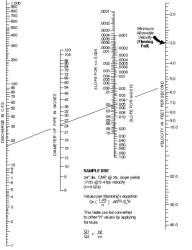
Each pipe within the system is sized and sloped such that its barrel capacity at normal full flow computed by Manning's equation is equal to or greater than the design flow. The nomograph in Figure F.2 may be used for an approximate solution of Manning's equation (Equation F.2). For more precise results, or for partial pipe full conditions, solve Manning's equation directly (Equation F.2) or use the discharge formula (Q = A * V) to solve for the volumetric flow rate (Equation F.3).
Equation F.2. Manning’s equation

where:
V = velocity (feet per second [fps])
n = Manning's roughness coefficient; see Table F.2
R = hydraulic radius = area/wetted perimeter (ft)
S = slope of the energy grade line (ft/ft)
Equation F.3. Volumetric flow rate equation

where:
Q = discharge (cfs)
V = velocity (fps)
A = area (sf)
n = Manning's roughness coefficient; see Table F.2
R = hydraulic radius = area/wetted perimeter (ft)
S = slope of the energy grade line (ft/ft)
Figure F.2. Nomograph for Sizing Circular Drains Flowing Full.
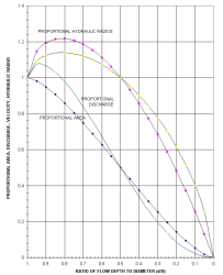
For pipes flowing partially full, the actual velocity may be estimated from the hydraulic properties shown in Figure F.3 by calculating Qfull and Vfull and using the ratio Qdesign/Qfull to find V and d (depth of flow).
Figure F.3. Circular Channel Ratios.
Table F.2 provides the recommended Manning's "n" values for preliminary design using the Uniform Flow Analysis method for pipe systems.
The "n" values for this method are 15 percent higher in order to account for entrance, exit, junction, and bend head losses.

