4.8.1 Flow Splitters
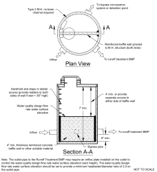
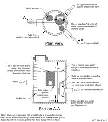
Two possible design options for flow splitters are shown in Figure II-4.14 and Figure II-4.15. Other similar designs that achieve the result of routing design flows to the target facility and diverting higher flows around the facility may also be acceptable.
Figure II-4.14. Flow Splitter Option A.
Figure II-4.15. Flow Splitter Option B.
4.8.1.1 Design Criteria
The following criteria shall be applied to the design of flow splitters. The term design flow rate used in the criteria in this section refers to any design flow rate, such as a water quality design flow rate or maximum flow rate to wetlands, above which flows shall be bypassed:
-
The top of the baffle wall shall be located at the water surface for the design flow rate (e.g., water quality design flow rate, maximum flow rate to wetlands, etc.). Remaining flows enter the bypass line. Flows modeled using a continuous simulation model shall use a 15‑minute time step.
-
The maximum head shall be minimized for flow in excess of the design flow rate. Specifically, flows to the target facility at the 100‑year water surface shall not exceed the design flow rate by more than 10%.
-
Either design shown in Figure II-4.14 or Figure II-4.15, or a similar design may be used.
-
As an alternative to using a solid top plate in Figure II-4.15, a full tee section may be used with the top of the tee at the 100‑year water surface elevation. This alternative would route emergency overflows (if the overflow pipe were plugged) through the target facility rather than back up from the manhole.
-
Special applications, such as roads, may require the use of a modified flow splitter. The baffle wall may be fitted with a notch and adjustable weir plate to proportion runoff volumes other than high flows.
-
For ponding facilities, backwater effects shall be included in designing the height of the standpipe in the manhole or vault structure.
-
Ladder or step and handhold access shall be provided. If the baffle wall is higher than 36 inches, two ladders, one to either side of the wall, shall be used.
4.8.1.2 Materials
-
The baffle wall may be installed in a Type 2 manhole or vault.
-
The baffle wall shall be made of reinforced concrete or another suitable material resistant to corrosion, and have a minimum 4‑inch thickness. The minimum clearance between the top of the baffle wall and the bottom of the manhole cover shall be 4 feet unless dual access points are provided.
-
All metal parts shall be corrosion resistant. Examples of preferred materials include aluminum, stainless steel, and plastic. Zinc and galvanized materials are discouraged because of aquatic toxicity. Do not use painted metal parts because of poor longevity.

