4.8.2
Flow spreaders function to uniformly spread flows across the inflow portion of runoff treatment BMPs (e.g., sand filter, bioretention swale filter strip). There are five flow spreader options presented here:
- Option A – Anchored plate
- Option B – Concrete sump box
- Option C – Notched curb spreader
- Option D – Through-curb ports
- Option E – Interrupted curb
Options A through C can be used for spreading flows that are concentrated. Any one of these options can be used when spreading is required by the facility design criteria. Options A through C can also be used for unconcentrated flows, and in some cases shall be used, such as to correct for moderate grade changes along a filter strip.
Options D and E are only for flows that are already unconcentrated and enter a filter strip or bioretention system. Other flow spreader options may be possible upon approval from Kitsap County.
4.8.2.1 Design Criteria
Where flow enters the flow spreader through a pipe, it is recommended that the pipe be submerged to the extent practical to dissipate energy as much as possible.
Flow spreaders are difficult to maintain to ensure that flow is evenly distributed. Flow spreaders shall not be used on slopes greater than 5% to prevent recombining of downstream flow that can create rills and gullies. Flow spreaders shall not be used in areas accessible by the public since walking on them can alter their flow characteristics.
For higher inflows (greater than 5 cfs for the 100‑year storm recurrence interval), position a Type 1 catch basin in the spreader and design the inflow pipe to enter the catch basin with flows exiting through the top grate. The top of the grate should be lower than the level spreader plate, or if a notched spreader is used, lower than the bottom of the v‑notches.
Option A – Anchored Plate
-
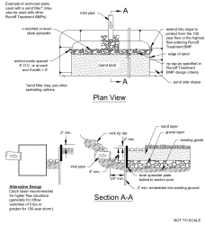
An anchored plate flow spreader (see Figure II-4.16) shall be preceded by a sump having a minimum depth of 8 inches and minimum width of 24 inches. If not otherwise stabilized, the sump area shall be lined to reduce erosion and to provide energy dissipation.
-
The top surface of the flow spreader plate shall be level, projecting a minimum of 2 inches above the ground surface of the runoff treatment BMP, or V‑notched with notches 6 to 10 inches on center and 1 to 6 inches deep (use shallower notches with closer spacing). Alternative designs may also be used.
-
A flow spreader plate shall extend horizontally beyond the bottom width of the facility to prevent water from eroding the side slope. The horizontal extent shall be such that the bank is protected for all flows up to the 100‑year flow or the maximum flow that will enter the BMP.
-
Flow spreader plates shall be securely fixed in place.
-
Flow spreader plates may be made of either wood, metal, fiberglass reinforced plastic, or other durable material. If wood, pressure treated 4‑ by 10‑inch lumber or landscape timbers are acceptable.
-
Anchor posts shall be 4‑inch-square concrete, tubular stainless steel, or other material resistant to decay.
Figure II-4.16. Flow Spreader Option A: Anchored Plate.
Option B – Concrete Sump Box
-
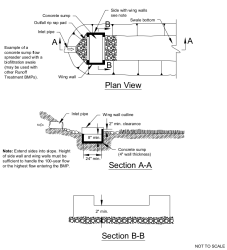
The wall of the downstream side of a rectangular concrete sump box (see Figure II-4.17) shall extend a minimum of 2 inches above the treatment bed. This serves as a weir to spread the flows uniformly across the bed.
-
The downstream wall of a sump box shall have “wing walls” at both ends. Side walls and returns shall be slightly higher than the weir so that erosion of the side slope is minimized.
-
Concrete for a sump box can be either cast-in-place or precast, but the bottom of the sump shall be reinforced with wire mesh for cast-in-place sumps.
-
Sump boxes shall be placed over bases that consists of 4 inches of crushed rock, 5/8‑inch minus to help ensure the sump remains level.
Figure II-4.17. Flow Spreader Option B: Concrete Sump Box.
Option C – Notched Curb Spreader
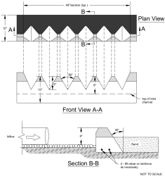
Notched curb spreader sections (see Figure II-4.18) shall be made of extruded concrete laid side-by-side and level. Typically five “teeth” per 4‑foot section provide good spacing. The space between adjacent “teeth” forms a v‑notch.
Figure II-4.18. Flow Spreader Option C: Notched Curb Spreader.
Option D – Through-Curb Ports
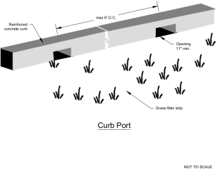
Unconcentrated flows from paved areas entering filter strips or bioretention swales can use through-curb ports (see Figure II-4.19) or interrupted curbs (Option E) to allow flows to enter the BMP. Through-curb ports use fabricated openings that allow concrete curbing to be poured or extruded while still providing an opening through the curb to admit water to the BMP. Openings in the curb shall be at regular intervals but at least every 6 feet (minimum). The width of each curb port opening shall be a minimum of 11 inches. Approximately 15% or more of the curb section length should be in open ports, and no port should discharge more than about 10% of the flow.
Figure II-4.19. Flow Spreader Option D: Through-Curb Port.
Option E – Interrupted Curb
Interrupted curbs are sections of curb placed to have gaps spaced at regular intervals along the total width (or length, depending on the BMP) of the treatment area. At a minimum, gaps shall be every 6 feet to allow distribution of flows into the BMP before they become too concentrated. The opening shall be a minimum of 11 inches. As a general rule, no opening should discharge more than 10% of the overall flow entering the BMP.


