F.2.2.1
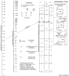
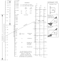
Nomographs such as those provided in Figure F.10 and Figure F.11 may be used to determine the inlet control headwater depth at design flow for various types of culverts and inlet configurations. These nomographs were originally developed by the Bureau of Public Roads—now the Federal Highway Administration (FHWA)—based on their studies of culvert hydraulics. These and other nomographs can be found in the Hydraulic Design of Highway Culverts, HDS No. 5 (FHWA 2012) or the WSDOT Hydraulic Manual (WSDOT 2019).
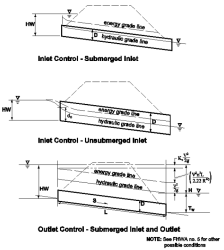
Figure F.9. Inlet/Outlet Control Conditions.
Figure F.10. Headwater Depth for Smooth Interior Pipe Culverts with Inlet Control.
Figure F.11. Headwater Depth for Corrugated Pipe Culvert with Inlet Control.
Also available in the FHWA publication, are the design equations used to develop the inlet control nomographs. These equations, Equation F.4 through Equation F.6, are presented below.
For unsubmerged inlet conditions (defined by Q/AD0.5 < 3.5), use Equation F.4 (Form 1) or Equation F.5 (Form 2). Refer to Table F.3 to determine the appropriate form of the equation to use.
Equation F.4. Headwater depth in unsubmerged inlet conditions (Form 1)
HW/D = Hc/D + K(Q/AD0.5)M ‑ 0.5S*
where:
HW = headwater depth above inlet invert (ft)
D = interior height of culvert barrel (ft)
Hc = specific head (ft) at critical depth (dc + Vc2/2g)
Q = flow (cfs)
A = full cross-sectional area of culvert barrel (sf)
S = culvert barrel slope (ft/ft)
K = constant; see Table F.3
M = constant; see Table F.3
* For mitered inlets, use +0.7S instead of -0.5S.
Equation F.5. Headwater depth in unsubmerged inlet conditions (Form 2)
HW/D = K(Q/AD0.5)M
where:
HW = headwater depth above inlet invert (ft)
D = interior height of culvert barrel (ft)
Q = flow (cfs)
A = full cross-sectional area of culvert barrel (sf)
K = constant; see Table F.3
M = constant; see Table F.3
For submerged inlet conditions (defined by Q/AD0.5 > 4.0), use Equation F.6.
Equation F.6. Headwater depth in submerged inlet conditions
HW/D = c * (Q/AD0.5)2 + Y ‑ 0.5S*
where:
HW = headwater depth above inlet invert (ft)
D = interior height of culvert barrel (ft)
Hc = specific head (ft) at critical depth (dc + Vc2/2g)
Q = flow (cfs)
A = full cross-sectional area of culvert barrel (sf)
S = culvert barrel slope (ft/ft)
c = constant; see Table F.3
Y.= constant; see Table F.3
*For mitered inlets, use +0.7S instead of -0.5S.
The specified head Hc is determined by Equation F.7.
Hc = dc + Vc2/2g
where:
Hc = specified head (ft)
dc = critical depth (ft); see Figure F.14
Vc = flow velocity at critical depth (fps)
g = acceleration due to gravity (32.2 ft/sec2)
Between the unsubmerged and submerged conditions, there is a transition zone (3.5<Q/AD0.5<4.0) for which there is only limited hydraulic study information. The transition zone is defined empirically by drawing a curve between and tangent to the curves defined by the unsubmerged and submerged equations. In most cases, the transition zone is short, and the curve is easily constructed.


