F.2.2.2
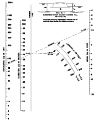
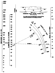
Nomographs such as those provided in Figure F.12 and Figure F.13 may be used to determine the outlet control headwater depth at design flow for various types of culverts and inlets. Outlet control nomographs other than those provided can be found in FHWA HDS No.5 or the WSDOT Hydraulic Manual.
Figure F.12. Head for Culverts (Pipe w/n = 0.012) Flowing Full with Outlet Control.
Figure F.13. Head for Culverts (Pipe w/n = 0.024) Flowing Full with Outlet Control.
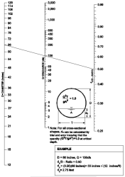
Figure F.14. Critical Depth of Flow for Circular Culverts.
The outlet control headwater depth may also be determined using the simple Backwater Analysis Method presented in F.2.1.2 Backwater Analysis Method for analyzing pipe system capacity. This procedure is summarized for culverts by Equation F.8:
Equation F.8. Outlet control headwater depth (Backwater Analysis Method)
HW = H + TW ‑ LS
where:
HW = headwater depth above inlet invert (ft)
H = Hf + He + Hex
Hf = friction loss (ft) = (V2n2L) / (2.22R1.33)
If (Hf + TW ‑ LS) < D, adjust Hf such that (Hf + TW ‑ LS) = D. This will keep the analysis simple and still yield reasonable results (erring on the conservative side).
He = entrance head loss (ft) = Ke * (V2 / 2g)
Hex = exit head loss (ft) = V2 / 2g
TW = tailwater depth above invert of culvert outlet (ft)
If TW < (D + dc)/2, set TW = (D + dc)/2. This will keep the analysis simple and still yield reasonable results.
L = length of culvert (ft)
S = slope of culvert barrel (ft/ft)
D = interior height of culvert barrel (ft)
V = barrel velocity (fps)
n = Manning's roughness coefficient; see Table F.2.
R = hydraulic radius (ft)
Ke = entrance loss coefficient; see Table F.4.
g = acceleration due to gravity (32.2 ft/sec2)
dc = critical depth (ft); see Figure F.14
The above procedure should not be used to develop stage/discharge curves for level pool routing purposes because its results are not precise for flow conditions where the hydraulic grade line falls significantly below the culvert crown (i.e., less than full flow conditions).


