4.4.2 Outfall Systems
4.4.2.1 Outfall Features
At a minimum, all outfalls shall be provided with a rock splash pad, unless the site requires a more robust energy dissipator. See the following bullets for guidance on outfall features, including other types of energy dissipation and appropriate uses for each.
-
The flow dispersion trenches shown in Figure II-4.1 and Figure II-4.2 shall only be used as an outfall.
-
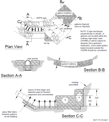
For outfalls with a velocity at design flow greater than 10 fps, a gabion dissipator or engineered energy dissipator shall be required. There are many possible designs.
The gabion outfall detail shown in Gabion Outfall Detail. is illustrative only. A design engineered to specific site conditions must be developed. Gabions shall conform to APWA/WSDOT Standard Plans for Road, Bridge and Municipal Construction.
-
Engineered energy dissipators, including stilling basins, drop pools, hydraulic jump basins, baffled aprons, and bucket aprons, are required for outfalls with design velocity greater than 20 fps. Design energy dissipators using published or commonly known techniques found in references such as the Hydraulic Design of Energy Dissipators for Culverts and Channels (FHWA 2006), Open Channel Hydraulics (Chow 1959), Hydraulic Design of Stilling Basins and Energy Dissipators (Peterka 1984), and other publications, such as those prepared by the Soil Conservation Service (now Natural Resource Conservation Service).
-
Alternate mechanisms may be used, such as bubble-up structures that eventually drain and structures fitted with reinforced concrete posts. If alternative mechanisms are considered, they require an individual approval and shall be designed using sound hydraulic principles and considering constructability and ease of construction and maintenance.
-
One caution to note is that the example gabion outfall (Figure II-4.7) may not be acceptable within the ordinary high water mark of fish-bearing waters or where gabions will be subject to abrasion from upstream channel sediments. Consider using a four-sided gabion basket located outside the ordinary high water mark for these applications.
Figure II-4.7. Gabion Outfall Detail.
4.4.2.2 Tightline Systems
-
Outfall tightlines may be installed in trenches with standard bedding on slopes up to 40%. In order to minimize disturbance to slopes greater than 40%, it is recommended that tightlines be placed at grade with proper pipe anchorage and support. At-grade tightlines shall be SWPE.
-
Outfall SWPE tightlines shall be designed to address the material limitations, particularly thermal expansion and contraction and pressure design, as specified by the manufacturer. The coefficient of thermal expansion and contraction for SWPE is on the order of 0.001 inch per foot per degree Fahrenheit. Sliding sleeve connections shall be used to address this thermal expansion and contraction. These sleeve connections consist of a section of the appropriate length of the next larger size diameter of pipe into which the outfall pipe is fitted. These sleeve connections shall be located as close to the discharge end of the outfall system as is practical.
-
Outfall SWPE tightlines shall be designed and sized using the applicable design criteria and methods of analysis specified for pipe systems in Vol II–4.4.1 Pipe Systems.
-
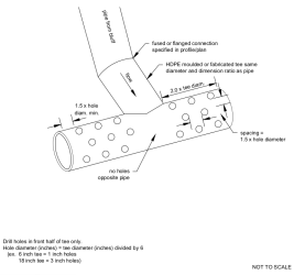
Due to the ability of outfall SWPE tightlines to transmit flows of very high energy, special consideration for energy dissipation shall be made. Details of an example "gabion outfall" are provided as Figure II-4.7. Details of a sample "tee type dissipator" are provided as Figure II-4.8.

