4.4.1 Pipe Systems
Pipe systems are networks of storm drain pipes, catch basins, manholes, inlets, and outfalls designed and constructed to convey surface water, including stormwater runoff. The hydraulic analysis of flow in storm drain pipes typically is limited to gravity flow; however, in analyzing existing systems it may be necessary to address pressurized conditions. A properly designed pipe system will maximize hydraulic efficiency by utilizing proper material, slope, and pipe size.
4.4.1.1 Design Criteria
All pipe material, joints, protective treatment, and construction workmanship shall be in accordance with WSDOT/APWA Standard Specifications, and AASHTO and ASTM treatment as noted under "Allowable Pipe Materials."
Allowable Pipe Sizes
See Table II-4.1 for allowable pipe sizes for pipe systems to be maintained by Kitsap County. For special cases where written approval is provided by the County Road Engineer, 8‑inch-diameter pipes may be allowed within the roadway right of way. Eight (8)‑inch-diameter pipe may also be allowed for privately maintained systems.
Allowable Pipe Materials
The following pipe materials are allowed for use in meeting the requirements of this manual. See WSDOT/APWA Standard Specifications for Road, Bridge, and Municipal Construction 7‑02, 7‑03, and 7‑04 for detailed specifications for acceptable pipe materials.
-
Plain and reinforced concrete pipe.
-
Corrugated or spiral rib aluminum pipe.
-
Ductile iron (water supply, Class 50 or 52).
-
Corrugated polyethylene pipe (CPEP)1.
-
Polyvinyl chloride (PVC)2 pipe.
-
Solid wall polyethylene (SWPE; also known as high-density polyethylene [HDPE] pipe or high-density polyethylene pipe [HDPP]) pipe3.
Allowable Pipe Joints
-
Concrete pipe shall be rubber gasketed.
-
Corrugated metal pipe (CMP) shall be rubber gasketed and securely banded.
-
Spiral rib pipe shall be "hat-banded" with neoprene gaskets.
-
Ductile pipe joints shall be flanged, bell and spigot, or restrained mechanical joints.
-
CPEP joints shall conform to the current WSDOT/APWA Standard Specifications for Road, Bridge, and Municipal Construction.
-
PVC pipe shall be installed following procedures outlined in ASTM D2321; joints shall conform to ASTM D3212, and gaskets shall conform to ASTM F477.
-
SWPE pipe shall be jointed by butt fusion methods or flanged.
Pipe Alignment
-
Pipes shall be laid true to line and grade with no curves, bends, or deflections in any direction. Exception:Vertical deflections in SWPE and ductile iron pipe with flanged restrained mechanical joint bends (not greater than 30°) may be allowed on steep slopes, provided the pipe drains.
-
A break in grade or alignment, or changes in pipe material shall occur only at catch basins or manholes.
Changes in Pipe Size
The following criteria apply to changes in conveyance pipe sizes (not including detention tanks):
- Increases or decreases in pipe size are allowed only at junctions and structures.
- When connecting pipes at structures, match any of the following (in descending order of preference): crowns, 80% diameters,4 or inverts of pipes. Side lateral connections5 12 inches and smaller are exempt from this requirement.
- Drop manholes may be used for energy dissipation when pipe velocities exceed 10 feet per second (fps). External drop manholes are preferred where maintenance access to the upstream pipe is preserved by use of a tee section. Internal drop structures may be approved only if adequate scour protection is provided for the manhole walls. Drop structures shall be individually engineered to account for design variations, such as flow rates, velocities, scour potential, and tipping forces.
- Downsizing pipes larger than 12 inches may be allowed provided pipe capacity is adequate for design flows.
Structures
Table II-4.1 lists typical drainage structures with corresponding maximum allowable pipe sizes.
-
Catch basin (or manhole) diameter shall be determined by pipe orientation at the junction structure. A plan view of the junction structure, drawn to scale, will be required for submittal with the site improvement plans (Volume II, Chapter 1) when more than four pipes enter the structure on the same plane, or if angles of approach and clearance between pipes is of concern. The plan view (and any sections if necessary) shall ensure a minimum distance between pipe openings of 8 inches for 48‑inch and 54‑inch catch basins, and 12 inches for 72‑inch and 96‑inch catch basins. The minimum distance between pipe openings shall be of solid concrete wall.
-
Evaluation of the structural integrity for H‑20 loading, or as required by the Kitsap County Road Standards (latest edition), may be required for multiple junction catch basins and other structures.
-
Catch basins shall be provided within 50 feet of the entrance to a pipe system to provide for silt and debris removal.
-
All SWPE pipe systems (including buried SWPE pipe) shall be secured at the upstream end. Where connecting to a structure, the downstream end shall be placed in a 4‑foot section of the next larger pipe size. This sliding sleeve connection allows for the high thermal expansion/contraction coefficient of this pipe material.
-
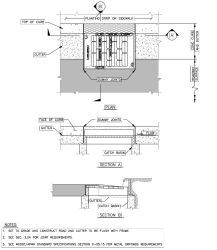
Through-curb inlets (see Figure II-4.3) are required on all catch basins located at roadway sags and in low points of cul-de-sacs.
-
The maximum slope of the ground surface for a radius of 5 feet around a catch basin grate or solid lid should be 5 horizontal to 1 vertical (5H:1V) to facilitate maintenance access. Where not physically feasible, a maximum slope of 3H:1V shall be provided around at least 50% of the catch basin circumference.
Figure II-4.3. Through-Curb Inlet.
Pipe Design Between Structures
-
Minimum velocity at full flow shall be 3 feet per second (fps). If site constraints result in velocities less than 3 fps at full flow, impacts from sedimentation in the pipe system shall be addressed with larger pipes, closer spacing of structures, sediment basins, or other similar measures.
-
Maximum velocity: 30 fps, except that there is no maximum velocity requirement for ductile iron pipe or butt welded SWPE.
-
Minimum slope for installed stormwater pipes shall be 0.5%.
-
SWPE tightlines down steep slopes are self-cleaning and do not require structures for maintenance.
-
The following maximum inlet spacings are recommended:
-
For roadway slopes less than 1%, maximum inlet spacing shall be 150 feet or less.
-
For roadway slopes from 1% to 3%, maximum inlet spacing shall be 200 feet or less.
-
For roadway slopes greater than 3% or design flows greater than 3 fps, maximum inlet spacing shall be 300 feet.
-
For structures with solid lids, the maximum spacing shall be 300 feet.
-
The maximum design water surface elevation in inlet structures shall be 1 foot below the top of the structure.
-
Pipe Cover
-
Pipe cover, measured from the finished grade elevation to the top of the outside surface of the pipe, shall be 2 feet minimum unless otherwise specified or allowed below. Under drainage easements, driveways, parking stalls, or other areas subject to light vehicular loading, pipe cover may be reduced to 1 foot minimum if the design considers expected vehicular loading and the cover is consistent with pipe manufacturer's recommendations. Pipe cover in areas not subject to vehicular loads, such as landscape planters and yards, may be reduced to 1 foot minimum.
-
Pipe cover over concrete pipe shall comply with Table II-4.2. For other pipe types, the manufacturer's specifications or other documentation shall be provided for proposed cover in excess of 30 feet.
Caution: Additional precautions to protect against crushing during construction may be needed under roadways if the road bed is included to meet minimum cover requirements. Damaged pipe shall be replaced.
-
For proposed pipe arches, the manufacturer's specifications or other documentation shall be provided for proposed cover.
|
Pipe |
Plain |
Class II |
Class III |
Class IV |
Class V |
|---|---|---|---|---|---|
|
12 |
18 |
10 |
14 |
21 |
26 |
|
18 |
18 |
11 |
14 |
22 |
28 |
|
24 |
16 |
11 |
15 |
22 |
28 |
|
30 |
|
11 |
15 |
23 |
29 |
|
36 |
|
11 |
15 |
23 |
29 |
|
48 |
|
12 |
15 |
23 |
29 |
|
60 |
|
12 |
16 |
24 |
30 |
|
72 |
|
12 |
16 |
24 |
30 |
|
84 |
|
12 |
16 |
24 |
30 |
|
96 |
|
12 |
16 |
24 |
30 |
|
108 |
|
12 |
16 |
24 |
30 |
|
Compaction Design A refers to the WSDOT Standard Plan for Pipe Bedding (B‑55.20‑02) |
|||||
Pipe Clearances
A minimum of 6 inches vertical and 3 feet horizontal clearance (outside surfaces) shall be provided between storm drain pipes and other utility pipes and conduits. When crossing sanitary sewer lines, the Washington State Department of Ecology criteria shall apply.
Pipe Compaction and Backfill
Pipe compaction and backfill shall be in accordance with the WSDOT Standard Plan for Pipe Bedding (B‑55.20‑02).
Pipe System Connections
Connections to a pipe system shall be made only at catch basins or manholes. No wyes or tees are allowed except on roof/footing/yard drain systems on pipes 8 inches in diameter or less, with clean-outs upstream of each wye or tee. Additional exceptions may be made for steep slope applications of SWPE pipe, as deemed prudent by geotechnical review.
Pipe Anchors
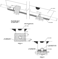
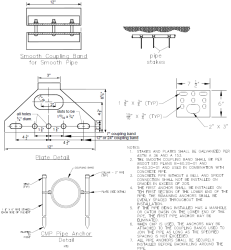
Table II-4.3 presents the requirements, by pipe material, for anchoring pipe systems, and Figure II-4.4 and Figure II-4.5 show typical details of pipe anchors.
|
Pipe Material |
Pipe Slope Above Which Pipe Anchors Required and Minimum Anchor Spacing |
Maximum Slope Allowed |
Maximum Velocity at |
|---|---|---|---|
|
CMP, Spiral Rib, PVC |
20% – (1 anchor per 100 LF of pipe) |
30%c |
30 fps |
|
Concrete or CPEPa |
10% – (1 anchor per 50 LF of pipe) |
20%c |
30 fps |
|
Ductile Ironb |
20% – (1 anchor per pipe section) |
None |
None |
|
SWPEb |
20% – (1 anchor per 100 LF of pipe, cross-slope installation only) |
None |
None |
|
Notes: fps = feet per second
|
|||
Figure II-4.4. Pipe Anchor Detail.
Figure II-4.5. Corrugated Metal Pipe Coupling and/or General Pipe Anchor Assembly.
Debris Barriers
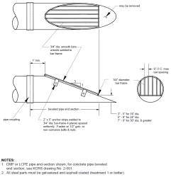
Debris barriers (trash racks) are required on all pipes 18 to 36 inches in diameter entering a closed pipe system. Debris barriers shall have a bar spacing of 6 inches. Refer to Figure II-4.6 and Vol II–4.5 Culverts for debris barrier requirements.
Figure II-4.6. Debris Barrier (in road right of way).
Outfalls
Outfalls shall be designed as detailed in Vol II–4.4.2 Outfall Systems.
Other Details
In addition to the details shown in Figure II-4.1 through Figure II-4.6, standard construction details are available in the APWA/WSDOT Standard Plans for Road, Bridge and Municipal Construction.
4.4.1.2 Methods of Analysis
This section presents the methods of analysis for designing new or evaluating existing pipe systems for compliance with the conveyance system capacity requirements.
Design Flows
Design flows for sizing or assessing the capacity of pipe systems shall be determined using the hydrologic analysis methods described in Vol II–4.2 Conveyance System Design Flow.
Inlet Grate Capacity
The methods described in the WSDOT Hydraulics Manual may be used in determining the capacity of inlet grates when capacity is of concern, with the following exceptions:
-
Use 100‑year design flows as computed per Vol II–4.2 Conveyance System Design Flow.
-
Assume grate areas on slopes are 80% free of debris; "vaned" grates, 95% free.
-
Assume grate areas in sags or low spots are 50% free of debris; "vaned" grates, 75% free.
Conveyance Capacity
Two methods of hydraulic analysis using Manning's equation are used sequentially for the design and analysis of pipe systems. First, the Uniform Flow Analysis method is used for the preliminary design of new pipe systems. Second, the Backwater Analysis method is used to analyze both proposed and existing pipe systems to verify adequate capacity. Each method is described further in Appendix F.
Use of the Uniform Flow Analysis method to determine preliminary pipe sizes is only suggested as a first step in the design process and is not required. Results of the Backwater Analysis method determine final pipe sizes in all cases. The director has the authority to waive the requirement for backwater analysis as verification.


