4.5 Culverts
Culverts are relatively short segments of pipe of circular, elliptical, rectangular, or arch cross section. They are usually placed under road embankments or driveways to convey surface water flow safely under the embankment. They may be used to convey flow from constructed or natural channels including streams.
This section presents the methods, criteria, and overview for hydraulic analysis and design of culverts. See Appendix F for details on the methods and standards to be used for hydraulic analysis and design.
4.5.1 Design Criteria
-
General
-
All circular pipe culverts shall conform to any applicable design criteria specified for pipe systems in Vol II–4.4.1 Pipe Systems.
-
All other types of culverts shall conform to manufacturer's specifications.
-
Minimum culvert diameters are as follows:
-
For cross-culverts under public and private roadways, minimum 18‑inch diameter shall be used.
-
For all other roadway culverts, including driveway culverts, minimum 12‑inch diameter shall be used.
-
-
No bends shall be permitted in culvert pipes.
-
Minimum cover over culverts shall be 2 feet under primary roads, 1 foot under secondary roads and in all roadside applications and on private property.
-
Maximum culvert length shall be 300 feet.
-
-
Headwater
-
For culverts 18‑inch diameter or less, the maximum allowable headwater elevation (measured from the inlet invert) shall not exceed 2 times the pipe diameter or arch-culvert-rise at design flow.
-
For culverts larger than 18‑inch diameter, the maximum allowable design flow headwater elevation (measured from the inlet invert) shall not exceed 1.5 times the pipe diameter or arch-culvert-rise at design flow.
-
The maximum headwater elevation at design flow shall be at least 1 foot below any road or parking lot subgrade.
-
-
Inlets and Outlets
-
All inlets and outlets in or near roadway embankments shall be flush with and conforming to the slope of the embankment.
-
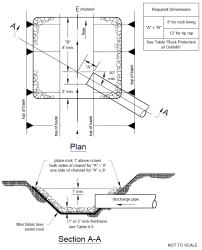
For culverts 18‑inch diameter and larger, the embankment around the culvert inlet shall be protected from erosion by rock lining or riprap as specified in Table II-4.4, except the length shall extend at least 5 feet upstream of the culvert, and the height shall be at or above the design headwater elevation. See Figure II-4.9 for a pipe culvert discharge protection detail.
-
Inlet structures, such as concrete end protection, may provide a more economical design by allowing the use of smaller entrance coefficients and, hence, smaller diameter culverts. When properly designed, they will also protect the embankment from erosion and eliminate the need for rock lining.
-
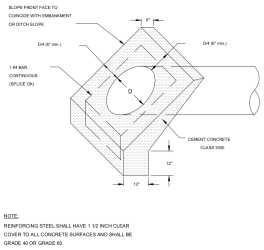
Concrete end protection is required for all CPEP, SWPE, and PVC pipe systems having exposed ends (see Figure II-4.10).
-
In order to maintain the stability of roadway embankments, concrete end protection, wingwalls, or tapered inlets and outlets may be required if right of way or easement constraints prohibit the culvert from extending to the toe of the embankment slopes. All inlet structures or end protection installed in or near roadway embankments shall be flush with and conforming to the slope of the embankment.
-
Debris barriers (trash racks) are required on the inlets of all culverts that are over 60 feet in length and are 18 to 36 inches in diameter. Debris barriers shall have a bar spacing of 6 inches. This requirement also applies to the inlets of pipe systems. See Figure II-4.6 for debris barrier details.
-
For culverts 18‑inch diameter and larger, the receiving channel of the outlet shall be protected from erosion by rock lining specified in Table II-4.4, except the height shall be 1 foot above maximum tailwater elevation or 1 foot above the crown, whichever is higher.
-
Figure II-4.9. Pipe/Culvert Outfall Discharge Protection.
Figure II-4.10. Concrete End Protection.
4.5.2 Methods of Analysis
Design Flows
Design flows for sizing or assessing the capacity of culverts shall be determined using the hydrologic analysis methods described in Vol II–4.2 Conveyance System Design Flow.
Conveyance Capacity
The theoretical analysis of culvert capacity can be extremely complex because of the wide range of possible flow conditions that can occur due to various combinations of inlet and outlet submergence and flow regime within the culvert barrel. An exact analysis usually involves detailed backwater calculations, energy and momentum balance, and application of the results of hydraulic model studies.
However, simple procedures have been developed where the various flow conditions are classified and analyzed on the basis of a control section. A control section is a location where there is a unique relationship between the flow rate and the upstream water surface elevation. Many different flow conditions exist over time, but at any given time the flow is either governed by the culvert's inlet geometry (inlet control) or by a combination of inlet geometry, barrel characteristics, and tailwater elevation (outlet control). See Figure F.9 in Appendix F for typical conditions of inlet and outlet control. The procedures presented in this section provide for the analysis of both inlet and outlet control conditions to determine which governs.
Inlet Control Analysis
Nomographs such as those provided in Figure F.10 and Figure F.11 in Appendix F may be used to determine the inlet control headwater depth at design flow for various types of culverts and inlet configurations. These nomographs were originally developed by the Bureau of Public Roads—now the Federal Highway Administration (FHWA)—based on their studies of culvert hydraulics. These and other nomographs can be found in the FHWA publication Hydraulic Design of Highway Culverts, HDS No. #5 (Report No. FHWA‑IP‑85‑15), September 1985; or the WSDOT Hydraulic Manual. See Appendix F for a detailed discussion on inlet control analysis.
Outlet Control Analysis
Nomographs such as those provided in Figure F.12 and Figure F.13 in Appendix F may be used to determine the outlet control headwater depth at design flow for various types of culverts and inlets. Outlet control nomographs other than those provided can be found in FHWA HDS No.5 or the WSDOT Hydraulic Manual. See Appendix F for a detailed discussion on outlet control analysis.

